
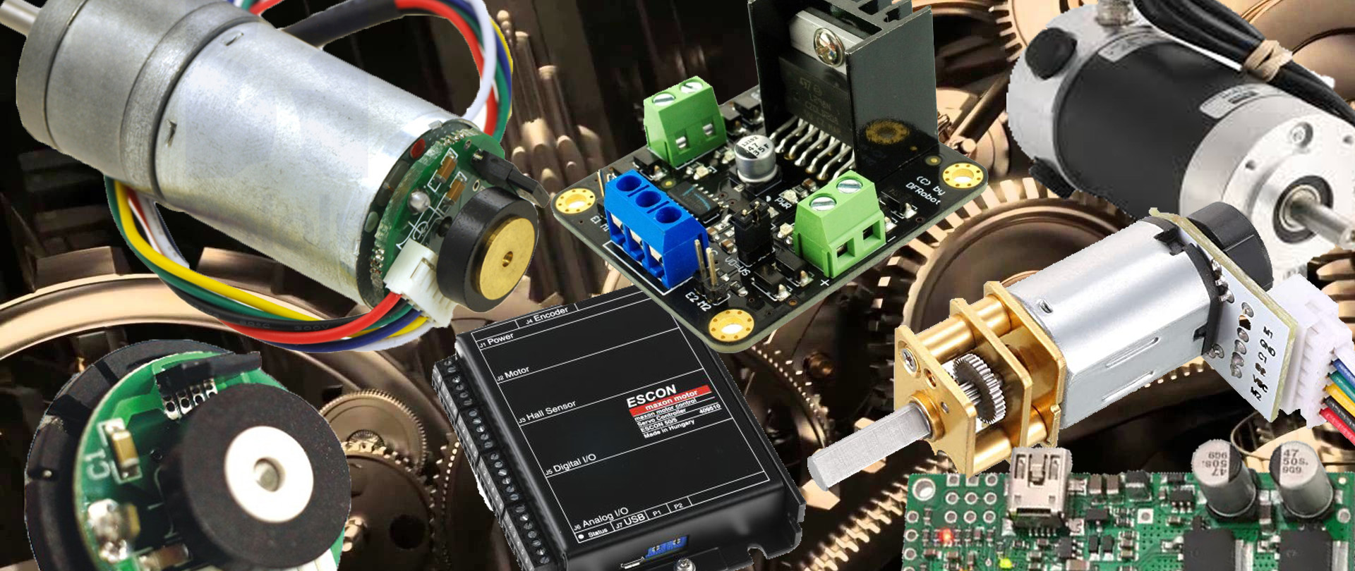
DC motors are commonly used in electronics and automation fields with a vast range of industrial, educational and hobby applications. Within this blog article we are going to discuss about some basic concepts and devices related to one of my experimental and hobby project related to a Robotics and PCB designing.
Post Content: This article will address following topics in order to get a basic understanding on some terms , devices and methods before we get in the closed loop Motor controller design part which I am giong to discuss in the next Blog article. You can skip reading this article if you already have an enough knowledge to understand the closed loop motor controlling concept .
Read Next: Designing a Closed Loop Motor Controller Article
- DC Motor Controller
- Open Loop vs. Closed Loop controlling
- Motor Encoder
- Closed Loop Motor controller
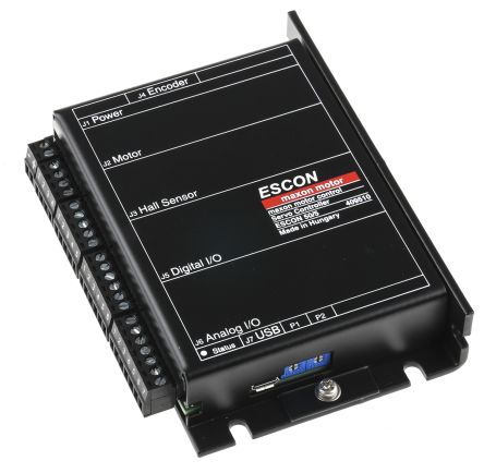
A DC Motor Controller
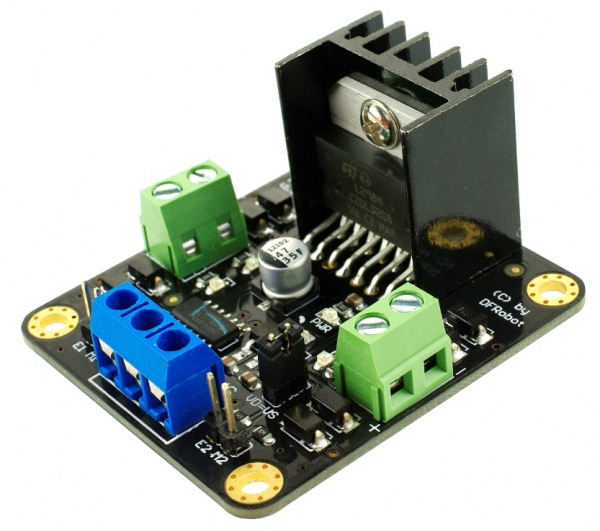
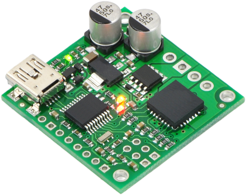
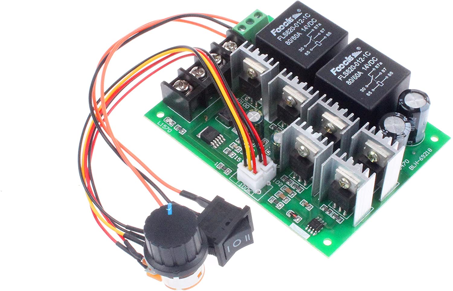
There are mainly two types of motor controllers as AC motor controllers and DC motor controllers. In my case I am going to give you a small introduction to brushed DC motor controllers. As you know, a DC motor manufacturers issue a Voltage rating for every motor and we can operate it on or below that voltage rating to have a safe operation.
Applying a constant voltage across the motor cause a approximately constant velocity of the motor shaft depending on the load on the motor shaft. However, in many applications, we need to achieve variable speeds. These speed commands may be issued by a microcontroller or a microprocessor according to the application through a standard communication protocol with low voltage signals.
The motor controller(Driver) comes to these applications as a linkage between main controller of the system and the motor. Job of a motor controller is to read speed and direction signals from the main controller which are in low voltages and use them to control the speed and direction of the motor by adjusting a higher or different voltage value and change the direction of the current flow.
What is a closed Loop Motor controller?
Basically every control system can be categorized in to two categories as Open loop control systems and Closed loop control systems. Since our intention is to understand a closed loop motor controlling, let’s get the idea of a closed loop system.
Closed Loop Vs Open Loop
Open Loop Control System : Let’s consider a system where an output is provided when an input is given to the controller unit. The first image shows an open loop system where the system outputs something only considering the input. Here the output is not measured and providing the output regardless of the output properties.
In most of the real world systems, output may vary by different amounts from the expected properties even if the controller issues a constant controlling signal due to real world situations. Let’s say we are steadily applying a 12V to a DC motor attached to a toy car on the floor. Due to the constraints like the friction, car may not move with a constant speed. Therefore, we need to monitor the output and adjust control signal accordingly to achieve the desired output properties. That’s why the closed loop systems are there to help us.
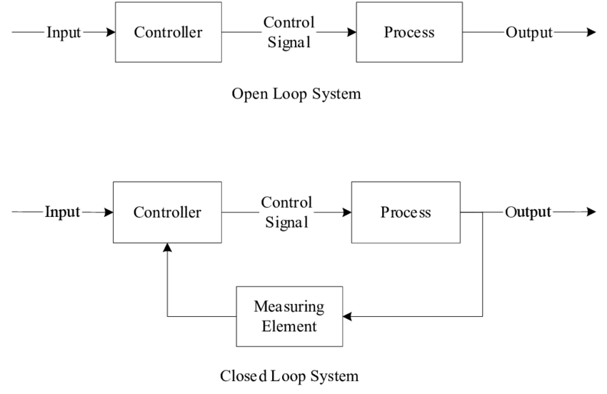
Closed Loop Control System : As you see in the illustration, part of the output is fed back to the controller through a measuring element such as a sensor which can measure the ceritain property. The Control signal is adjusted by mixing feedback and input reference signals in an appropriate manner to issue the correction control signal to the process unit.
Therefore, a system with a feedback from its own output, in order to automatically regulate the process to achieve a desired property is said to be a closed loop control system.
Closed Loop Motor Controller
I think you got an idea about a general closed loop system. Let’s get back in to our topic which is the closed loop motor controller. In most of real life applications with motors, there may be some fluctuations of the output due to friction between actuator contacts and also because of small changes in power supplies.
Therefore, we need to have a feedback in order to achieve a desired constant speed/specific speed profile/desired direction or desired position of the shaft.
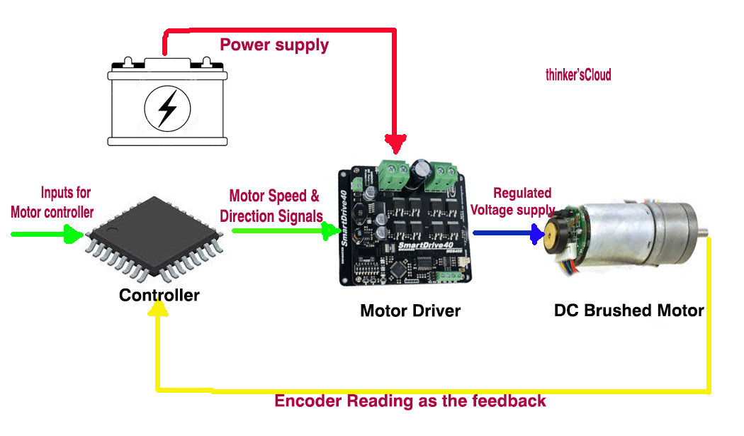
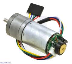
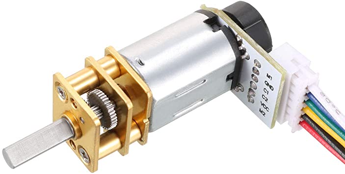
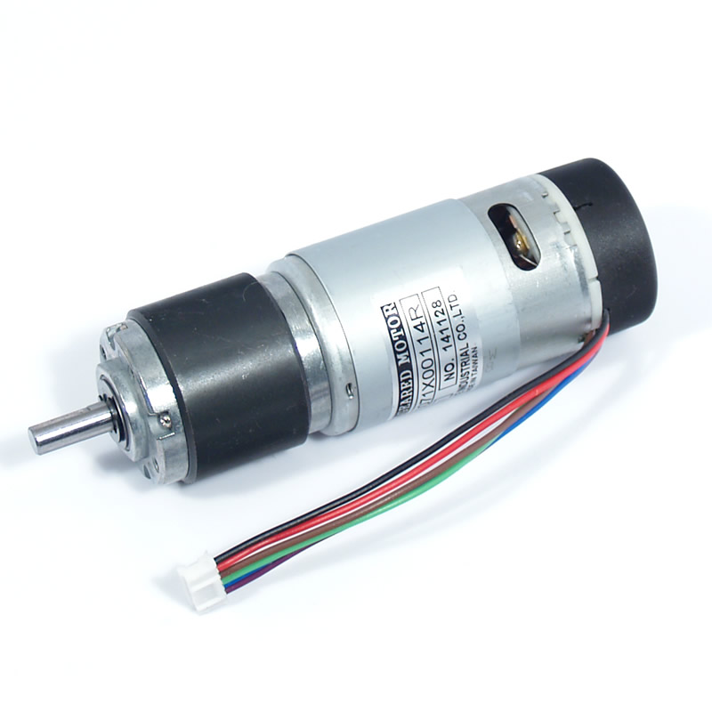
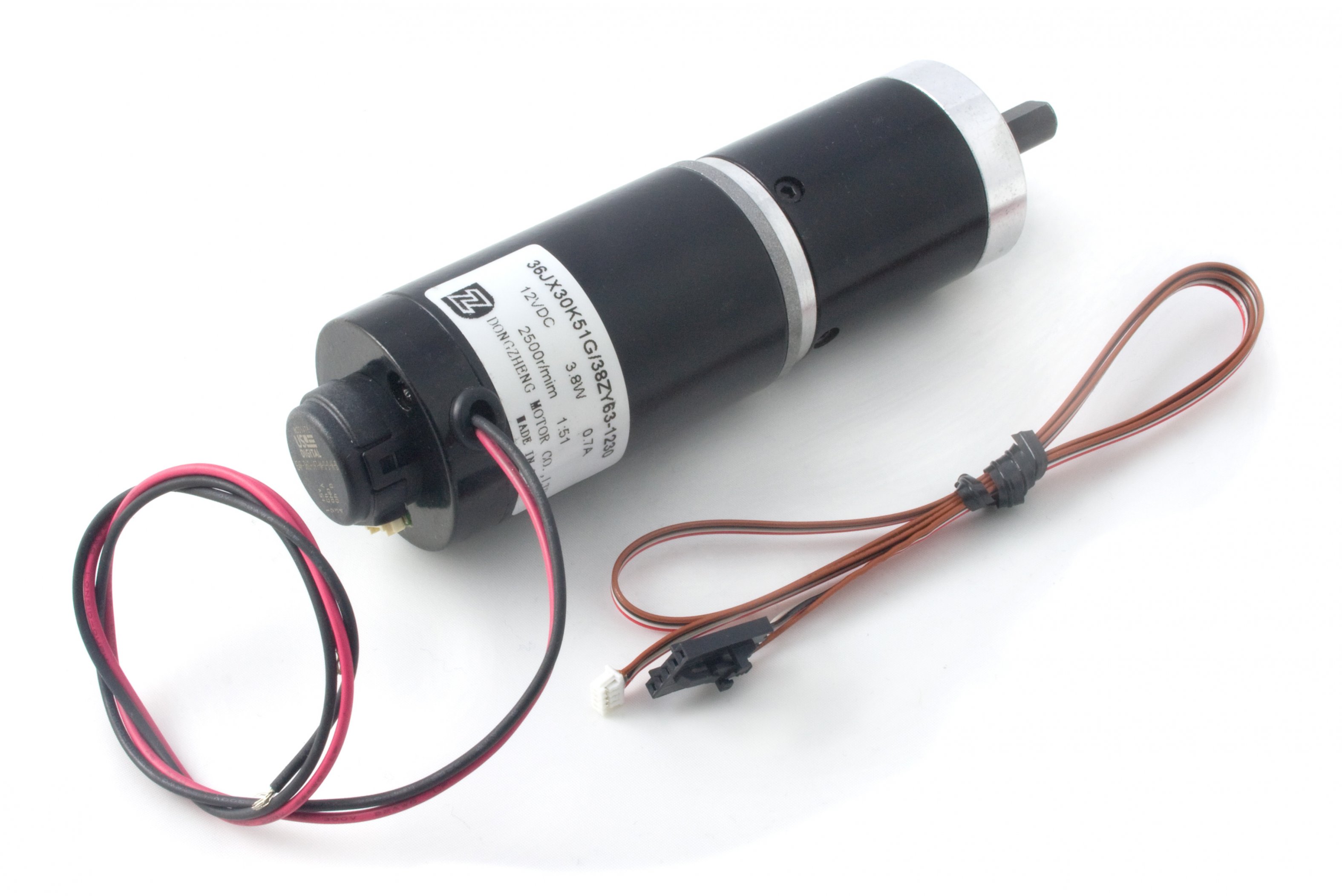
In order to have it, we need to measure the output properties of the motor which can be the speed, direction or position while it is running. To measure them we need to use some kind of sensors. In our case we are considering only DC brushed motors. Wheel encoders are the most available monitoring element for measure above properties. Some manufacturers provide built-in magnetic type encoders specially for DC gear motors. Most of them have two outputs in order to monitor the direction as well, other than the revolutions count.
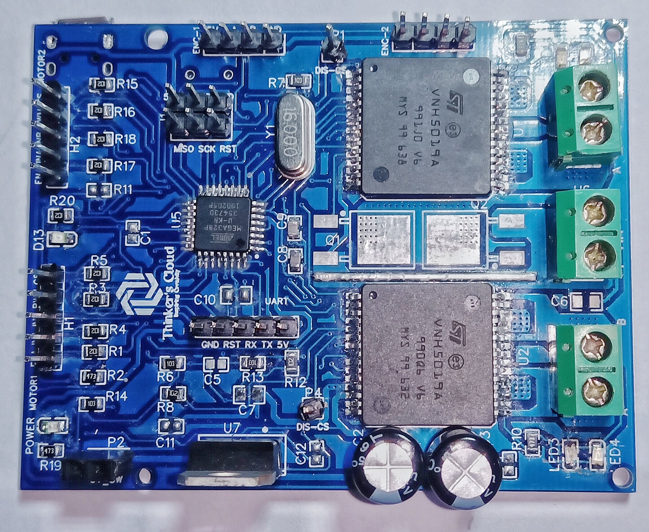
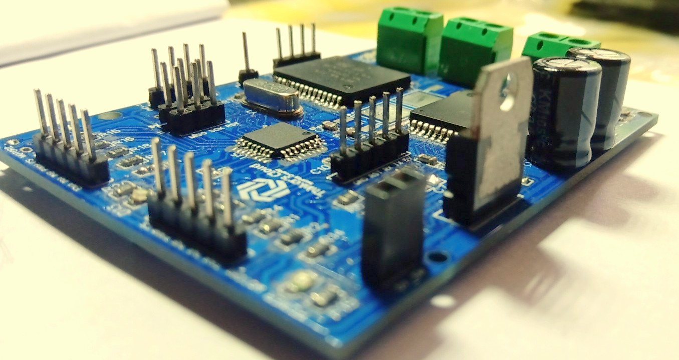
As I mentioned in the motor controller part, the input commanding signals are issued by a controlling unit of the application. In the above illustration, you can see minimal components set of a closed loop motor controller with controlling signals, controlled voltage output and the feedback portion from the encoder counter readings.
Motor Encoder Explanation
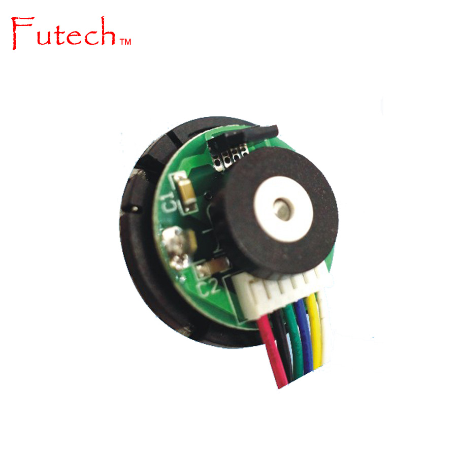
Encoder is a sensor which can be used to measure amount of rotation of a shaft. Generally, a rotary encoder attached to the rear par of the motor shaft is used as the motor encoder. Purpose of having an encoder for a motor is to measure some properties of the rotation such as direction and amount of revolution.
There are two major types of rotary encoders availbale in the market as follows.
-
Absolute Encoders: They Provide the current position of the shaft which can also used as an angle transducer
-
Incremental Encoders: Provide the continuous information about the motion of the shaft which can bes used to deduct speed and position.
Processing absolute type encoder data is bit complex compared to processig of incremental encoder data. Within this article, we are consider only about the incremnetal type encoders. If you would like to know more informations about rotary encoders, use the following link.
More Information About Rotary Encoders
Normally, an Incremental encoder gives one or more channels of outputs having a square shaped pulses or ticks as the motor is running. Let’s take a look at what are those output signals and how they get triggered.
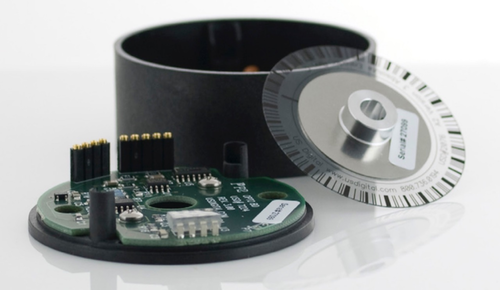
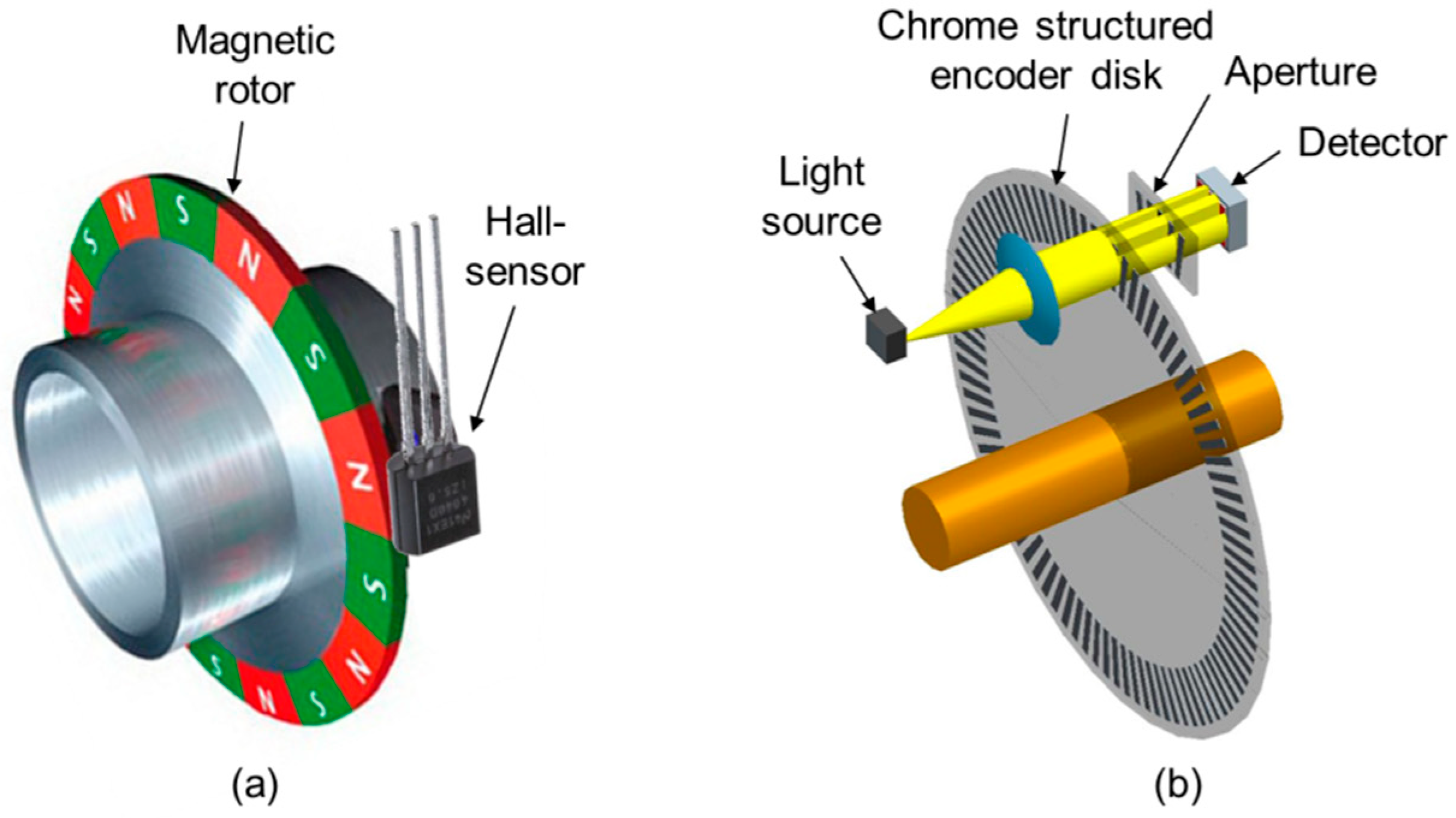
Incremental encoders also have different technologies. Optical encoders and Magnetc encoders are the common types used in many applications. Among these two types majority of DC motors are having built-in Magnetic Encoders.
Above animation shows how these magnetic encoders in a motor gets its readings using two magnetic sensor heads. The rotating circle represents a disk with a special ferromagnetic pattern as illustrated which is rigidly attached to the shaft of the motor. A and B represent the two outputs from sensors.
Using Encoders to Detect the Direction of Rotation
Motor shaft rotating direction can be either clockwise or anti-clockwise. We can use two outputs from an incremental encoder to easily detect this direction. The following illustration will show you cleary the process of detection.
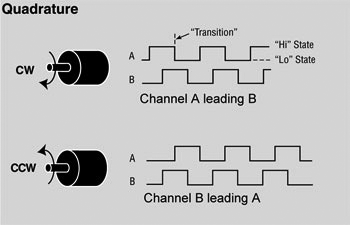
As you see in the above image and in the animation, output pulse trains of two channels are not in the same phase at a certain time instance. If we read both the channels from a processing unit, we can find which channel gives the HIGH state of the pulse train before the other channel. This is same as finding which channel gives the state transition before the other one. Signal rising from LOW to HIGH or A signal falling from HIGH to LOW is called as a stste transition.
In the above illustration, if the motor shaft rotates in to the clockwise direction, its channel A leads the channel B at a certain time instance. Vice versa counter clockwise rotation will gives a leading output for channel B. This channel reading part can be implemented in a processeing unit of the motor controller to achieve a better closed motor controlling.
Put Them All Together
I hope now you have a basic idea on DC motors, motor controllers and closed loop control systems. Now it is time to conclude the article with reviewing the big picture. Just applying a constant or variable voltage supply to a motor without monitoring output will not give the expected movement in many real world motor applications due to practical restraints like friction.
Using feedback information from an encoder, we can achieve smoother movement profiles from a motor because if the output is not at the desired level we can adjust it accordingly. Rotary encoders are the easiest and best way to get this feedback from motors. Closed loop motor drivers have following advantages over open loop ones.
Advantages of Closed Loop Motor controlling
- A constant torque or constant speed can be achieved against a variable load
- Higher accuracy with fine controlling ability
- Higher dynamic response
- Advanced smoothing and speed profiles can be implemented
- Easiness in integration with upper level of any application
With this basic introduction to the Closed loop motor controlling, let’s move on to my next article which is a robotics related project on designing a closed loop motor controller for development applications.
If you have any question or need to clarify something related to the content of this article, please do not hesitate to put a comment below or contact me in that matter.
Read Next Part: Designing a Closed Loop Motor Controller Article


Leave a comment