
DC motors are commonly used in electronics and automation fields with a vast range of industrial, educational and hobby applications. Closed loop motor controlling may offer a smooth and precise control with a less effort for the developers. Within this blog article we are going to discuss one of my experimental and hobby project related to robotics and electronics.
Note: If you do not have a clear idea on closed loop motor controlling or need to clarify any detail regarding this area, I suggest you to read the previous blog article written by me on basics of closed loop motor controlling..
Read Previous Article: Basics of Closed Loop Motor Controlling
Introduction to Closed Loop motor controller
Since we discussed some basics of motor controlling and taking feedback from motors to measure output properties in my previous blog article, I am not going discuss them here. Just applying a constant or variable voltage supply to a motor without monitoring output may not give the expected movement in many real world motor applications due to practical constraints like friction. Using feedback information from an encoder, we can achieve smoother movement profiles from a motor because, if the output is not at the desired level we can adjust it accordingly.
Advantages of Closed Loop Motor controlling
- A constant torque or constant speed can be achieved against a variable load
- Higher accuracy with fine controlling ability
- Higher dynamic response
- Advanced smoothing and speed profiles can be implemented
- Easiness in integration with upper level of any application
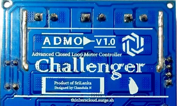
Introduction to My Design: Challenger Motor Controller
Design Considerations
Since we are dealing with many experimental and academic related robotics projects, I decided to design a DC brushed motor controller with development features. That means, this motor controller can be used as a normal open loop motor controller as well as can be programmed to your custom closed loop operations.
Many available cheap motor controllers are not capable of handling considerably large currents and many of them are open loop motor controllers. Commercially available closed loop motor controllers are expensive and some of them are not open source. Therefore, I went through following design considerations according to expected applications, further development and economic factors.
- Load current
- Operating Voltage
- Communication protocols
- Processing Unit
Best way to implement a DC motor driver is, using H-bridge configurations per each single motor in order to achieve both clockwise and counter clockwise direction driving. We can use four MOSFETs(Metal Oxide Semiconductor Field Effect Transistor) to build each H-bridge as the following schemetics.

However, this process consumes more PCB space and additional components to MOSFET gate drivers, protection monitoring, etc. Therefore, I chose an IC which have this full H bridge circuit with most of the essential peripheral components inside within itself.
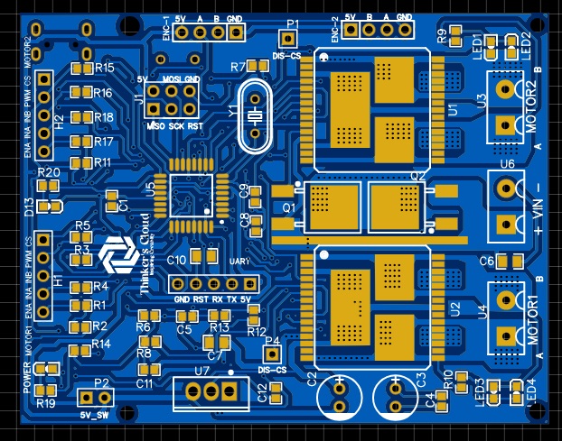
Components of My Design
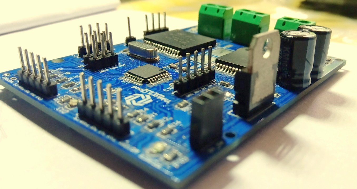
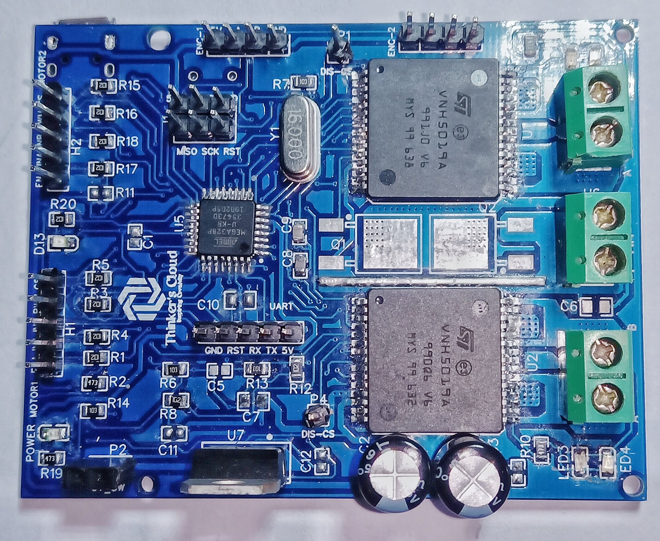
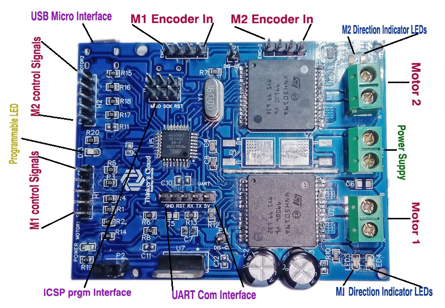
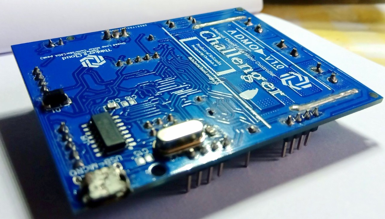
The following figure shows you, all the ports for signal inputs/outputs , communication ports, programming ports, motor connecting screw block terminal connectors and power ports of my challenger closed loop motor controller.
Components Selection
Motor Driver H-Bridge
As I mentioned above, I selected ST Electronics’ VNH5019A-E Full H-bridge IC which is capable of handling one DC brushed motor with speed and direction adjustments. This Motor driver can handle continuous 12A current and Peak 30A current through the motor. This higher current carrying capability is the most attractive specification of this IC. Other than that, low power consumption, current sensing capability, automatic under/over voltage shutdown and protection are some other cool specs in choosing this product over other ICs.
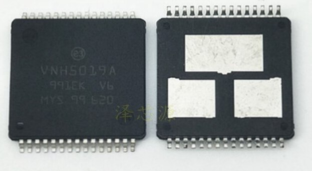
Here you can see three thermal pads underneath the IC in order to maintain an excellent thermal flow from the die to the PCB.
More Information About VNH5019 Driver
Controller
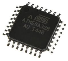
Since we are going to implement a closed loop motor controller we need to have in-built processing unit to process encoder readings and process this data to provide corrected control signals to our VNH5019 H bridge. Since this is an experimental and hobby related project, I selected Atmega328P-AU microcontroller, because it provides all the required input/output pins, communication protocols and someone can program it using Arduino, C or C++ easily using existing tools and software.
Communication
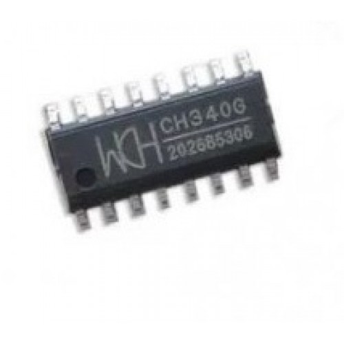
Communication between the VNH5019 and Atmega328 is happening through PWM pins or Digital input/output pins since it is the recommended way by the manufacturers of the H-bridge. Since this must be a user friendly device, plug and play kind of Communication method can be added. Therefore, I chose a USB to UART converter IC which is CH340 to easily plug the device to your PC or Laptop via a USB micro cable to programming and data receiving purposes.
Modular Design Approach
Motor driver
Main component of the design is the Motor driver. Many of mobile robotics projects are equipped with at least two motors. Having two motors driver capability in one motor driver is an advancement for a developer. Therefore, I added two VNH5019 full H-bridges to the design. Each H-bridge have four input pins as Enable, In 1, In 2 and the PWM (Pulse Width Modulation) input. PWM input is for speed command for the motor. Up to a frequency of 20KHz PWM signal can be given for this. Direction of the rotation is given by the in1 and in2 pins. Enable pin will enable and disable the H-bridge when we input High and Low signals respectively.
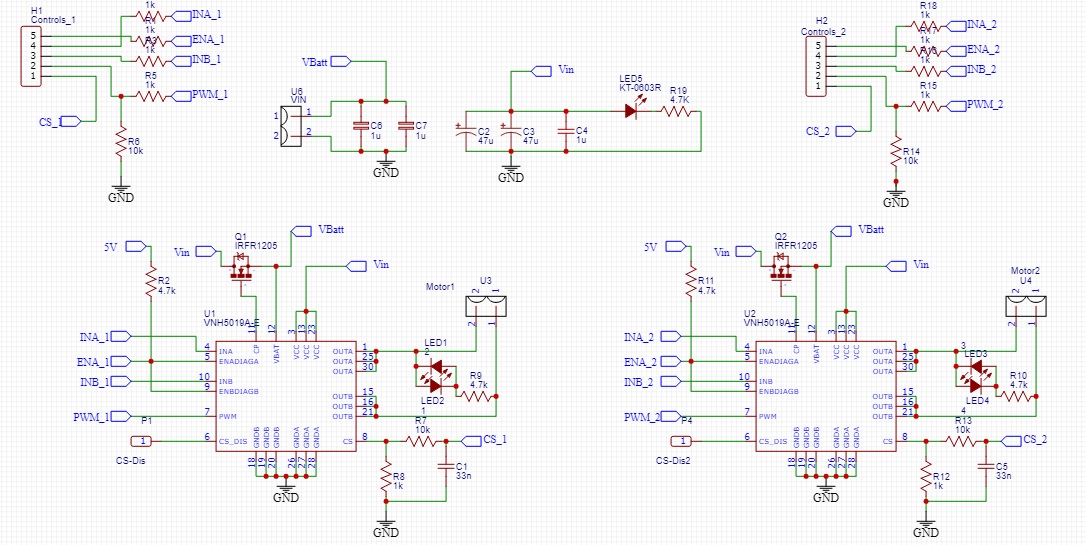
You can see in the schematic of the Motor driver unit drawn using the Easy EDA software. I selected this software to draw the circuit schematics and the PCB CAD drawing because, PCB footprint libraries for many of the commercially available electronic components are there in this software due to the vast community contributions. The other reason is this software is issued by the JLC PCB company china which I used to send these PCB designs and get them printed. It is really easy to place that order through this software directly.
Controlling Part
Main functionality of this unit is to issue speed and direction commands to the above discussed motor driver part. In order to do this, encoder channel outputs of both motors are connected to the interrupt pins of Atmega328 chip. Encoder reading, error calculation, correction signal generation parts are doing inside this unit using a kind of correction algorithms like PID (Proportional Integral Derivative).
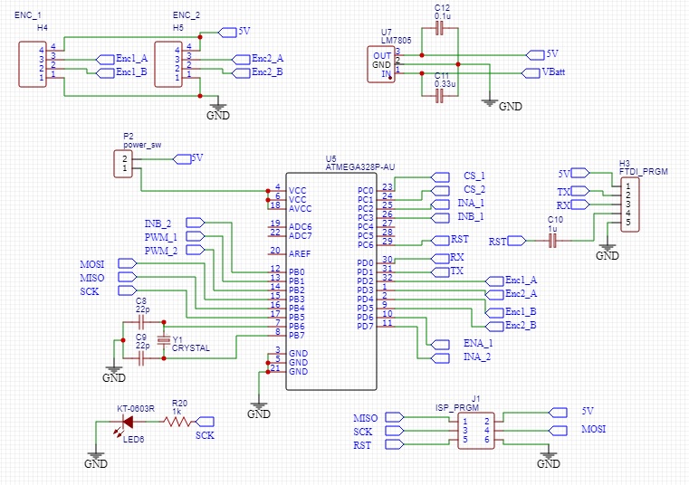
As you can see in the schematic, a regulated 5V supply for the atmega328 controller is generating within this unit using a regulator IC. Since, this is a closed loop controller, and to be user friendly I placed serial UART interface which takes user inputs to connect this whole unit to the main controller of your project. Programming the unit can be done through the USB micro interface or the ISP (In-System Programming) programming interface with male headers.
Communication
This is the final part of the design which is the CH340 USB to Serial UART converter based programming and communication interface. If there is no this kind of USB feature you need to find a separate FTDI converter or another programmer separately to program this device which is not a good user friend design.
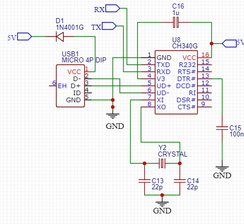
Other than these things, if the user needs to use this as an open loop motor controller, that also okay with this design because, all the signal input pins for the motor driver are taken as male headers to manually give signals by overriding the atmega328 control unit.
PCB Design
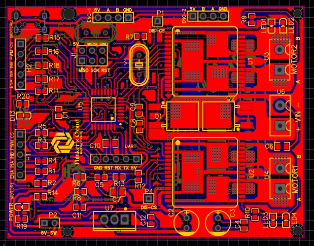
After finalizing the whole circuit, drawing and double checking each module, I moved on to draw the PCB CAD design. Main consideration of this part was designing it as compact as possible. Inexpensive and compact way was to break this circuit in to two PCB layers. Placing input output headers and sockets in the proper places going through practical considerations was an important thing like any other PCB design. Otherwise you may end up in a big trouble when you try to solder them or plug and detach jumpers to your final product.
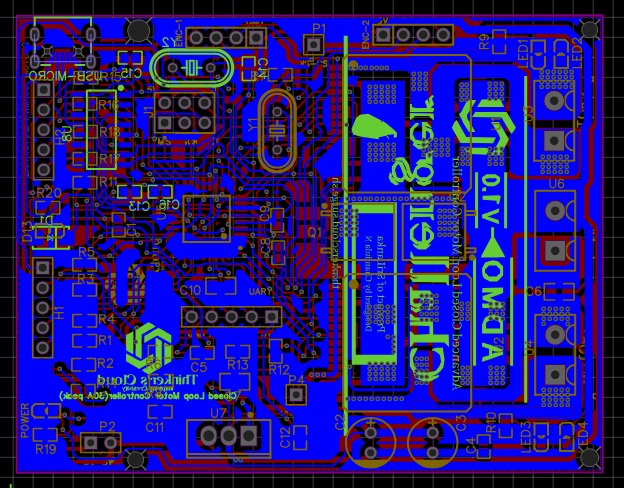
Important Facts on PCB design
As you can see, I have placed copper tracks in different trace sizes. The reason behind this was an extremely important fact which is different current flowing ratings though each copper track. Current carrying capability of copper tracks are basically depending on trace width, copper thickness and coper material properties.
Signals carrying tracks coming and going out from the Atmega microcontroller are actually carrying several tens of mili ampheres. Therefore, I placed traces with small trace widths (10milis) for those tracks. Supply and motor driving copper tracks may carry huge currents up to 30A. Therefore, I placed coper zones with higher widths as they can carry the amount of current they are supposed to carry without any harm to the tracks.
Here, I have used the via stitching option which gives us an array of copper plated holes connecting upper and bottom side layers of the PCB improving the current carrying capability and both sides connectivity.

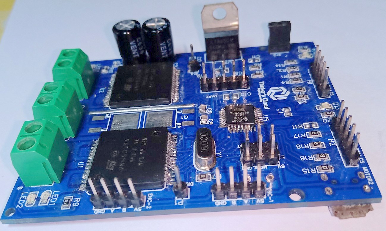
Testing the Challenger Motor Controller
I did basic testings for my first soldered challenger prototype using one of my previous robot design project which is a six wheeled mobile robot platform with the Rocker Bogie suspension configuration.
I selected this robot to test my motor controller because, this robot contains six motors to achieve the mobility. Therefore, it draws a considerably high current for all six motors while moving though a rocky area…(Just like a Mars Rover moves on the rocky terrain of Mars). This helped me to check the maximum current drawing capabilities of my conroller.
Read Rocker Bogie Suspension System Article
I did not upload the closed loop controlling code I used for the testings. You can use ICSP programming interface to upload the Arduino bootloader to the Atmega328chip and do coding easily with your usual arduino IDE without a trouble. You can read my Program Atmega328P microcontroller via Arduino board as an ISP Programmer article in this blog to easily catch up if you don’t know how to do that.
It’s time to wrap up this discussion. I can give you the circuit schematics and PCB CAD drawings if you are interested in, or you can design one of your own awesome motor driver with this knowledge.Contact me if you are willing to see the CAD drawings and do not hesitate to comment bellow if you have any question regarding the content of this article.


Leave a comment