
Designing a Micro Robot on a PCB
Micro robots are becoming popular in robotics and hobby electronics fields rapidly since they have several positive factors with comparison to the bulky designs. Generally, a design of a micro robot is heavily limited by its size and obviously by its hardware components because of they are designed to be light weight.
Since these types of robots are designed according to a specific application like swarm-robots, micro mouse or even for educational purposes, we can design them with specific set of hardware which won’t get affected by above limitations that much. Designing of a micro robot can be bit difficult due to its highly compact nature. However, the same compact nature can make the assembling process easier and the building cost lower compared to a regular sized robot.
One of the key advantages of these type of robots is that the whole hardware assembly can be done on a single circuit board or a stack of circuit boards. It makes them compact and cheaper. Here in this post I am going to discuss on designing a micro mobile robot with four wheels, which is targeted to be a general purpose development robot platform. I will explain the design considerations, how to design the modular schematics, PCB drawing and printing PCBs with a PCB manufacturing Company..
Design Considerations of the Micro Robot
Base
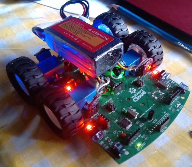
Basically my target was to design a four wheeled mobile platform with individual motor for each wheel and all the peripherals are embedded in a single printed circuit board. Actually the four wheeled design can also be achieved using only two motors with a simple gear plus bearing set rather than using four motors. However, there is some mechanical part over that implementation and therefore here I chose the simple individual motor design for each wheel. In addition to above two four wheeled designs, this kind of robots can be implemented with two driving wheels plus a free rolling caster ball or a caster wheel. Following images show different design approaches for the same kind of robot platform.
Motors and wheels
Since we are interested in designing a micro robot, we cannot use large wheels or bulky motors with big gear boxes. In that case we have a huge advantage, because there’s no need of driving a heavy load due to the light weight design of the robot and still we are using four motors to drive that load. Speed of the motors is also a critical factor according to your application. Since I am designing a general purpose robot, according to my experience and the availability in the market, a considerably medium range RPM value such as 200RPM or 300RPM will be enough for my application.
In this case I used a two cell Li-ion or Li-Po battery (7.2V) as the power supply to the robot. Therefore, I selected 6V motors for my purpose. With above specifications I found micro metal gear motors with plastic brackets available in the online market. These motors are ideal for smaller robot designs since they can provide a desirable torque with the metal gear box.I found a set of plastic wheels which can be fitted in to the above motor shafts with the “D” shaped slot. Selecting the diameter is depending on your application. I chose the following wheels for my project.
Controller
Obviously the heart of any kind of embedded system is its controller. It can be a microprocessor, micro-controller, FPGA or any kind of programmable logic device. For a micro robot, most of the time it will be a micro-controller since it’s easy to program using a common programming language /IDE and interface all the required peripheral devices to it through I/O pins. In the selection process of a matching microcontroller, first of all we need to identify the required processing power to handle all the processes. In my design I have added an IR line detecting sensor panel (QTR panel) with 8 sensors, 4 front facing IR emitting LEDs and photo diodes to wall detecting task, 3 sonar sensors in three sides, 2 dual H bridge motor drivers for 4 motors, encoder reading interfacing for two motors, an IMU sensor, an I2C AMOLED display for monitoring or debugging purposes and additional I2C and UART ports for extensional purposes. For all the above mentioned peripheral devices, we need to have a considerable number of I/O pins from the microcontroller. Since it is cheaper and easy to deal with the Arduino IDE, I selected two Atmel Atmega328P-AU surface mounting microcontrollers which can make the design more compact. Communication between two microcontrollers is happening via I2C protocol. Motor controlling, IR sensor array reading, I2C slaves handling and some other tasks are assigned to one chip and the rest of are done by the other chip.
Motor Controller
As I discussed in the motor selection sub section, I need to control four DC micro metal gear motors with the specifications of 6V operating voltage and 1.5A stall current. Since this is a light weight application and need to control four motors, I selected MX1919 motor driver ICs with dual H bridges inside each package. They are available in the market at a very cheap cost and can operate in the 2V-10V supply voltage range. Each H bridge is capable of driving a maximum current of 2.5A. I used two of these ICs for my design. Main advantage of this model is, we can complete the motor driver with lesser amount of extra components other than the IC itself.
Critical Components for the Design
ATMEL Atmega 328p-AU microcontrollers MX1919 dual H-bridge motor drivers Micro Metal Gear DC Motors (6V brushed)
Modular Design Approach
The next step of our design process is implementation of the CAD drawings of the whole robot’s circuit schematics. Since this is a considerably complex circuit with a large number of components, the best approach is to broke the whole schematic into small modules and connect them through the labeled nets. In my design there are three circuits as follows and used the Altium Designer 16.0 electronic design software package for this design.
- Main controller module and power distribution
- Sub controller
- Motor controller
We will discuss each of them briefly as following.
Main controller module
This schematic is based on the first Atmega 328P micro controller chip and its peripheral interfaces. QTR panel, encoder reading for one motor, ISP programming interface, I2C port, UART port for Bluetooth communication or FTDI programmer interface are the features included in this module. Other than that, we have the power distribution circuit as well within this module. Since all the sensors we are using and the two Atmega328 chips are working on 5V we need to regulate 5V from the Li-Po battery we are going to use as the power source. Therefore, I placed several ports for plug a switching buck converter and several other switches including main power switch and the motor controller power switch in this module.
Sub controller Module
The second Atmega micro-controller and its peripherals are the main parts of this module. Wall or obstacle detecting front 4 IR sensors, 3 sonar sensors into three sides, Encoder readings for one motor, a buzzer, I2C interface, UART interface for FTDI programming and ISP programming interface are the peripherals which get connected to the second micro-controller chip.
Motor Controller
As we discussed earlier, I have used two MX1919 dual H bridge motor controlling ICs in my design. Since this IC package contains most of the components needs to implement the dual H bridges, we have to place only two zenar voltage regulators and two capacitors to complete the motor controller.
Competed Circuit schematics can be found in the following link: https://github.com/ChandulaNethmal/MicroBot-1
PCB Design
After completing the schematic designs by connecting each module on separate sheets using labels for each net, we need to do the most difficult and time consuming task of the project which is the PCB designing part. Here I used the Altium PCB designer to do the task. Since there are lots of components to be integrated in a small circuit board, organization of the component assembly is very critical. First of all, we need to define a board shape according to our purpose and shape. I chose a simple shape as the following images shows. In the front of the robot I placed the QTR panel, IR sensors, Sonar and two micro-controller chips. Then four motors are placed in the rear side of the board considering wheel and motor dimensions. Motor controlling part is placed in the middle of the PCB and power management and switches are placed in the far rear side of the PCB. You can customize this orientations according to your need.
For the routing purpose I selected a two-layer PCB design since we have to route a complex circuit in a small space. Thicknesses of each copper trace is very important because they must be capable of carrying different amount of currents according to the type of the trace. As an example, a copper trace carrying current to a motor must be capable of carrying at least the stall current of that motor. Micro-controller I/O traces may be thinner than a power supply traces since they are carrying a less amount of current.
Finally, I added a Copper polygon pour to both top and bottom copper layers and assigned labels and texts to each port and component on the Top overlay layer (Silk layer) and competed the design by placing some mounting holes for motor brackets and the PCB itself.
Following images shows that the both sides of the PCB from the design view and 3D view.
You can find the completed Altium PCB drawing from the
following link: https://github.com/ChandulaNethmal/MicroBot-1


Leave a comment